Managing IoT devices and telemetry
Managing the flow of data from devices in the field to an IoT data platform can be challenging. When supporting devices from multiple vendors, using different communication protocols, then adding complications such as device replacement during field maintenance or multiple data destinations and you end up with a puzzle that needs more than the usual ‘deliver messages from A to B’ solution that most IoT platforms support.
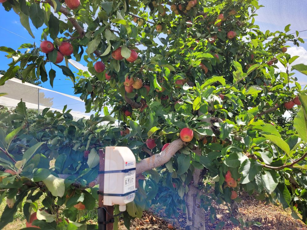
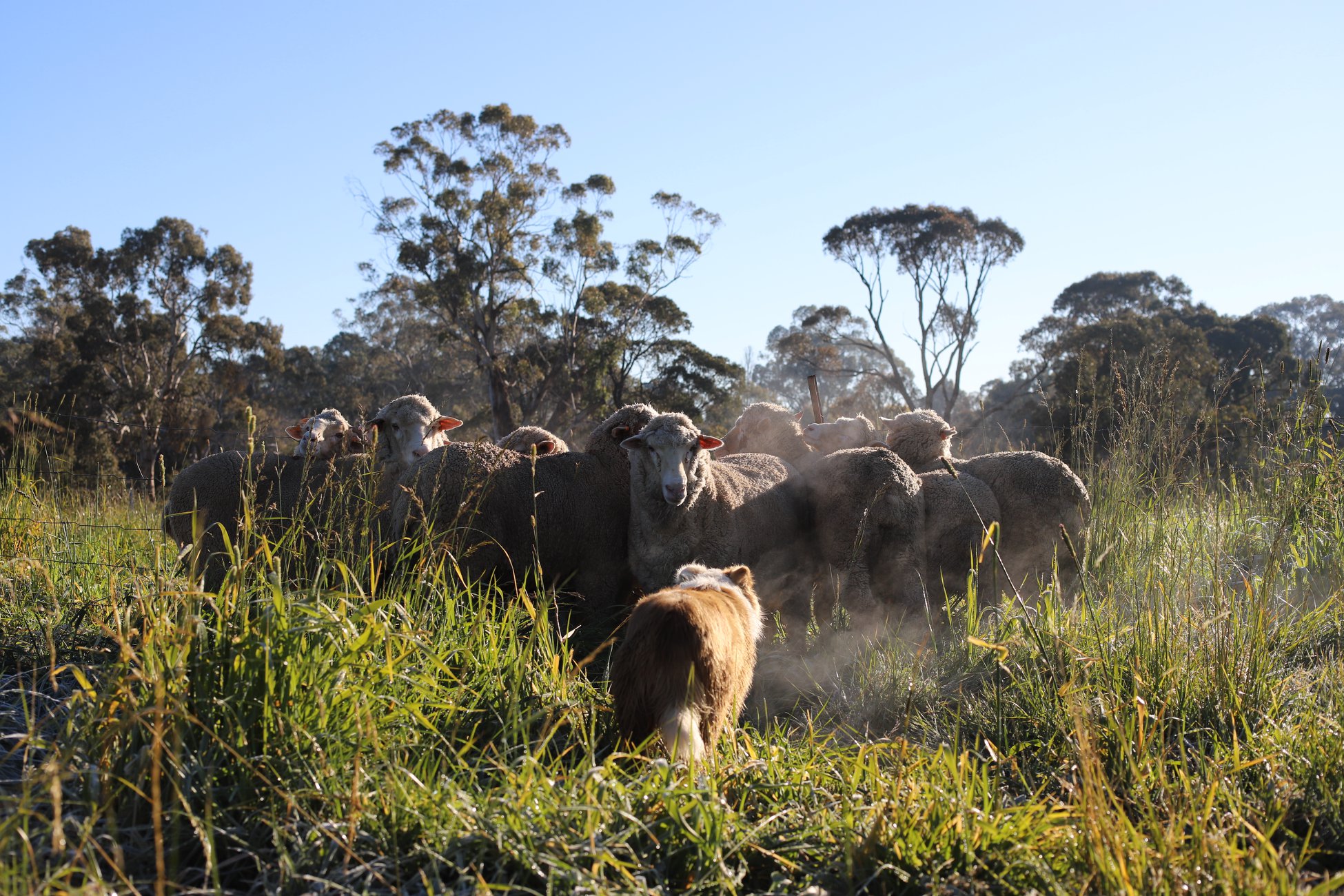
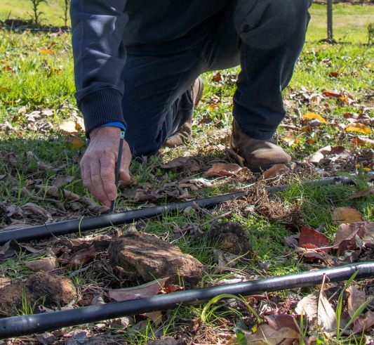
The Climate Smart Pilots team has a varied set of devices to manage in often harsh environments. We encounter problems ranging from buoys getting run over by boats or washed away during flood events to sheep and cockatoos chewing on cables however much shielding we add. Part of our project is testing devices for suitability on farms and some of them just aren’t up to the conditions, despite claiming IP67 rated housings. So we have a busy field maintenance program and replace numerous devices each year.

As explained below, unless you can find a vendor who supplies the devices, the back-end system, and the user-facing application that cover your requirements, the IoT in its current state is a veritable Tower of Babel. We cannot take advantage of any single vendor’s curated ecosystem due to both our varied pilot projects, and our role in trialling many types of commercial sensors, and developing our own custom sensors. We have recently brought a new system online, called IoTa, to help manage this complexity. IoTa provides the necessary flexibility in receiving, decoding, routing, and delivering IoT traffic from and to multiple systems.
The following figure gives a high-level view of IoTa’s architecture. On the left are the vendor-/protocol-specific modules responsible for receiving or fetching messages and decoding them, pushing them into the system in a standard format. The middle area shows the process responsible for routing the messages from real-world devices to logical devices to enable data continuity in the face of device breakdowns. Finally, on the right are modules responsible for delivering the mapped telemetry to destination systems. Each of these layers are explained in more detail below.

How are messages received?
The IoT is a complicated environment, still relatively new and constantly evolving. It can be said communications in the IoT are converging upon JSON (JavaScript Object Notation - a method of encoding data) over MQTT (the Message Queuing Telemetry Transport protocol for sending data), which are well defined and popular standards for transferring data, but there are still many instances where this is not the case.
Even if it was, it leaves many interoperability questions unanswered. It is like saying people all talk with their mouths and listen with their ears… but with no agreement on what language they speak or the etiquette of talking and listening in turn. In some cases two people will both be listening, assuming the other will talk; or both might be talking over each other with neither hearing what is said.
In the case of the IoT, there is not yet any agreement on how messages are delivered or what format (language) they are written in. To address this problem, IoTa uses receiver modules that know how to listen for or fetch messages from a particular vendor or service, and how to decipher those messages. These modules then send the decoded message onwards through IoTa in an internally standardised format for further processing and delivery.
Finally, most current IoT platforms do not record the original message from a device, and it is lost after the values are decoded and recorded. IoTa receiver modules store a copy of the message as it was received in a database. This is useful both for diagnostic purposes, and allows messages to be reprocessed if required.
When we need to receive data from a new service, we write another of these modules. There are three so far, covering messages from The Things Network, Green Brain, and YDOC. These receivers cover three different ways of getting messages, and provide a good base for other receivers if the need arises.
Who or where is this message from?
All devices have some form of identifier that can be found either in their messages, or in how the message is delivered. So, it is always possible to determine which real world device sent the message.
However, on farms we are interested in recording the data associated with particular locations - we want a continuous set of values spanning any device replacements that happen due to failures. So we cannot simply record data from every device against ‘itself’. Data should be recorded against a particular location such as a tank, field, or vehicle regardless of which real world device is installed there at present.
In light of the above we have implemented the concept of physical and logical devices. A physical device is something in the real world, installed at some place for some amount of time. A logical device represents a location of interest. That location may be fixed or it may move, but it represents something data should be associated with independently of which device sent the data at any given moment.
To illustrate the distinction between a system that only knows about physical devices and how IoTa allows physical devices to be associated with a logical device over time, the following figure shows the scenario of a water tank having two physical sensors, and how charts of the readings look in the two systems. On the left, the system that only knows about physical devices can only show two charts to cover the time span that data has been collected. In contrast, the right hand side shows how an IoT platform driven by IoTa can display the data from the tank, rather than from the two sensors that have been installed in it. 
Bridging physical and logical devices
When a message arrives from a physical device, IoTa must determine which logical device that message should be delivered to. The bridge between these two devices is called a mapping. In the simplest case, if a current mapping exists - the physical device is associated with a logical device - and the message can be sent on. However, with a long-running IoT system, there are subtleties to be considered.
When a message from a device arrives, IoTa can check if it is known and if not, create a representation of that device - a physical device - in the system. However it should not automatically create a corresponding logical device and start delivering messages. The reasoning behind this is that the new physical device may be sitting in a lab being tested or commissioned so is not yet associated with any actual location, and in any case the data being sent is not useful. So these messages should be ignored other than for us to see the device is working.
A similar case is when a device in the field is sending obviously bad data. It is useful to be able to switch off the flow of data from that device to the destination(s), while still receiving the messages in case later analysis is useful. In this case the existing mapping between the bad physical device and the logical device can be paused.
The figure below illustrates how two tank level sensors (physical devices) have their telemetry messages routed to a single logical tank level sensor, with a gap in the readings for that logical device between the first physical sensor failing and the new one being installed. The first physical device stopped sending when it broke, and messages from the replacement physical device begin being recorded against the logical device after the device mapping is updated. If the broken device is repaired and switched on, its messages will not be routed to the logical device because its mapping was ended when the new device mapping was created.

If devices are refurbished and reinstalled in the field, possibly in a different place, then that physical device will have multiple mappings recorded against it. For example, it may have been mapped to logical device X for some period of time, then be taken out of commission for a while, then put back into the field at the place represented by logical device Y.
Finally, this idea of mapping physical devices to logical devices over time allows re-analysis of messages as they were received because it is possible to reconstruct the timeline of which device was in a particular place at any given time. An example of when this is useful is if a bug is found in a message decoder that meant some values were interpreted incorrectly. With the mapping history in place, and the set of messages ‘as received’ stored by the various receivers, it is possible to reconstruct the timeseries data for a particular logical device.
Where should this message go?
The delivery of telemetry has its own wrinkles. Over the course of the project we have changed where we store our data and prior to IoTa there was no clean way to start sending data to the new platform. In addition to switching platforms over time, we may in future wish to send data to multiple destinations simultaneously to allow other projects to take advantage of our message processing system to handle their own IoT deployments.
In the same way that messages from devices come in different formats, there is no agreement among IoT platforms in how they accept data. They may accept data in plain-text or JSON, over MQTT, HTTP REST APIs, or a direct TCP socket connection. Their device definitions have varying systems of identification information, and may be limited in how many variables or channels of information they can store.
As with the receiving end of the system, the delivery end of the system has been designed to allow multiple modules to receive the decoded telemetry messages that should be forwarded to logical devices. Each module knows how to deliver the data to its particular platform. Like the message receivers, these modules can be quite small and relatively simple to write.
IoTa presently has one delivery module, sending data into Ubidots.
The information stored by IoTa will assist in future changes by allowing us to send incoming data onto new systems, while back-filling data in those systems using the as-received messages and device mapping history if necessary.
Conclusion
This article has provided a high-level overview of the problems encountered deploying and running a non-trival IoT system which uses devices from many vendors, talking different protocols, with different message formats. It describes our solution to the IoT Tower of Babel and discusses the issues that arise due to replacement of failed devices in the field, and how IoTa assists in overcoming the subsequent data continuity problem.
In summary, IoTa provides the following benefits:
- Reception of data from different vendors via multiple connection options - push, polled, different protocols.
- Storage of the telemetry messages ‘as received’ to allow re-processing of the messages if necessary.
- Enabling continuity of data by decoupling the physical device currently in the field from the logical device representing that installation.
- An architecture that allows new receiver and delivery modules to be added with well a defined message format for data flow between them.
Related Case Studies