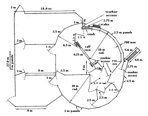
Circular cattle yard: 250 head capacity
Good yard design
When planning and constructing stockyards, it is important to ensure that operator safety is carefully considered, e.g. it is important that the yards are designed so that the stock handler is able to easily move out of danger should the need arise (see Agfact E2.7 Self-locking cattle gate latches).
Yard features
This yard plan (Figure 1) combines the more modern circular working area with a network of rectangular holding/feeder yards. It has been built by a number of producers in NSW and works extremely well.

The rectangular holding yards are an important part of the yard plan to comfortably accommodate 250 cattle and to allow a rapid flow of cattle into and out of the main working area. The yard design features a long curved race, round yard drafting, separate calf race, fully circular flow of cattle, and one-person operation.
Construction materials
The preferred materials are a combination of pipe or railway line posts with sawn timber rails. However, the choice will depend to a large degree on availability of materials and personal preference.
Posts are either 75 mm galvanised or black pipe, with plate steel (150 × 100 mm) drilled and welded to bolt the rails onto, or 250 to 300 mm timber posts.
Race and forcing yard
These are made with sawn timber rails 150 × 50 mm. The internal width of the race should be 700 mm but no wider.
On the curved race the internal width at the entrance from the forcing yard to the race should be widened to 750 mm to allow a smoother flow of cattle into the race and reduce possible bumping of hips.
The posts should be a minimum of 1050 mm in the ground, concreted in and braced to the adjoining post with a threaded or welded steel bar a little below ground level.
It is also advisable to be able to remove the lower rail for the full length of one side of the race in case cattle go down or get legs caught under the bottom rail. The bottom two rails in each panel can also be hinged in a gate frame which can be raised in the case of cattle going down.
For husbandry procedures carried out in the race, a catwalk 460 mm high on the working side allows easy access over the top of the cattle. In this situation the top rail can be replaced by a 38 mm pipe rail or a 32 mm capping pipe rail placed directly above the top timber rail to reduce operator injury.
Care should be taken to keep all the measurements of the forcing yard as specified, as changes in the angle of approach into the race may affect the flow of cattle.
The worker access should be included as specified to give easy access into the forcing yard from the race working area.
If the loading ramp is located as shown in the diagram, the gate panel leading into the ramp should be sheeted in with sheet metal or rubber belting.
Round yard
The posts should be located to allow each gate to swing both ways for ease of drafting and to allow the filling of the round yard from the various feeder/working yards.
For greater strength the posts can be extended to 2.6 m above the ground and tied overhead with 38 mm pipe.
Holding/working yards
The outer holding yards and the curved fenceline up to the entrance of the forcing yard can be constructed of cable with a pipe capping rail. The forcing yard, round yard, adult race and calf race should be of timber or pipe construction.
Siting the yard
The yard should be centrally located on the property, with good road access for trucking of stock in all weather conditions. The ideal site is a gravelly ridge with a gentle slope down to the north-east for good drainage and quick drying in wet weather.
It is important to run the race up and around the slope for smooth cattle flow, as cattle tend to baulk when running downhill. The cattle will also flow better if they are moving back towards the paddocks or holding yards from which they have just come.
Pegging out
The starting point will depend upon whether the yards are sited to accommodate existing fencelines or are free of existing restrictions.

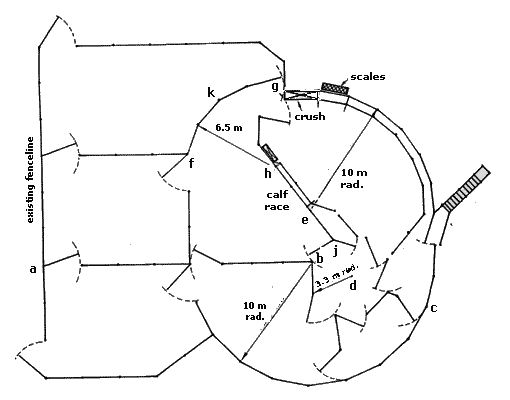
From an existing fenceline, locate point a , and extend a line from a 22 m to point b so that the line a–b is at right angles to the existing fenceline. Point b is the centre for the bottom curved fenceline on a 10 m arc. Locate the posts along this arc at 3 m intervals up to the start of the forcing yard. Spacings then change to 2.5 m.
To locate the centre of the round yard, string line can be run from point b to c , and a distance of 3.3 m from b measured to locate point d (centre). An arc of 3.3 m is inscribed and the posts are located from point b at 2.5 m intervals.
Point e is the centre of the upper curved fenceline and is located 4 m from point b such that the line e–b is at right angles to a–b . An arc of 10 m is inscribed and the post location is continued from the lower arc, at 2.5 m intervals, to the crush.
The centre of the upper curved fenceline f–g is point h . It is located by inscribing an arc 6.5 m long from point f and g ; h is the point of intersection of these two arcs.
The fenceline for the calf race is located on the straight line between point j on the round yard and point k .
Acknowledgment
This Agfact was originally written by R. J. Wilton of NSW Agriculture.

